
Related Products
How We Designed a Machine-Tending Cell with a Composite Robot and Receiving AGV
In this machine-tending project using a composite robot and receiving AGV, the challenge was not simply to have a robot load and unload workpieces from a...
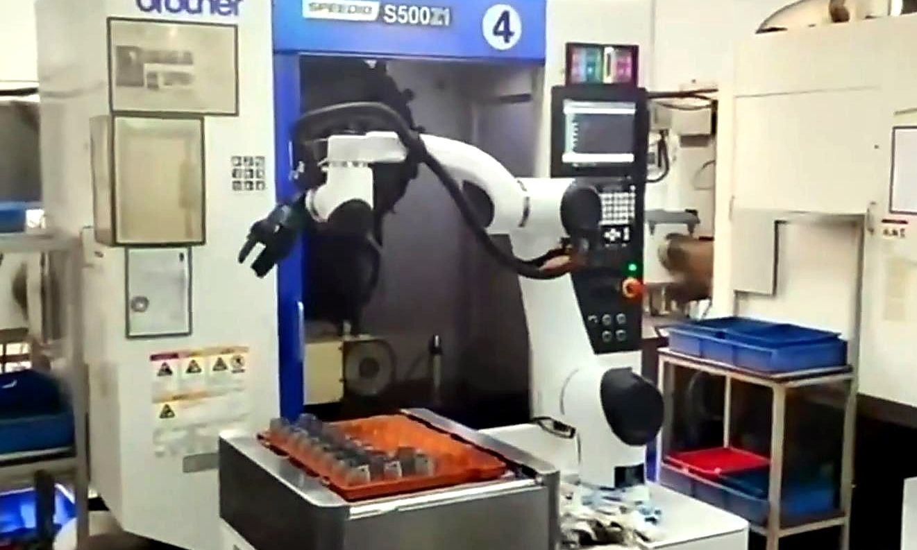
In this machine-tending project using a composite robot and receiving AGV, the challenge was not simply to have a rob...
In this machine-tending project using a composite robot and receiving AGV, the challenge was not simply to have a robot load and unload workpieces from a machine.
The entire automation cell needed to handle raw-material receiving, workpiece loading, unloading after machining, pallet transfer, and the handoff of processed materials to the surrounding intralogistics system. The final system therefore combined a composite robot, a receiving AGV, transfer stations, roller conveyor modules, electric grippers, and safety components.
What we really needed to design was not one robot, but an entire material cycle:
How raw materials enter the automation cell, how the robot performs machine loading and unloading, and how processed materials return to the factory logistics system.
This is why we did not treat the robotic arm, AGV, and conveyor equipment as separate machines. Instead, we designed the cell around the complete material flow.
Why Adding a Robotic Arm Alone Was Not Enough
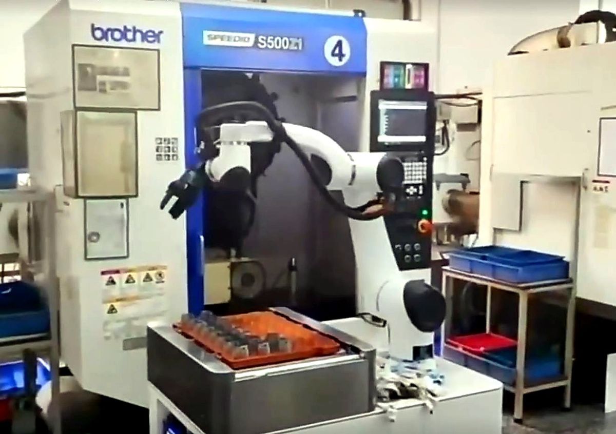
If we look only at the machine-loading and unloading operation, the requirement appears straightforward:
- Pick up the raw workpiece.
- Load it into the machine.
- Wait for machining to finish.
- Remove the processed workpiece.
- Place it at the designated location.
From this perspective, installing a robotic arm next to the machine might appear sufficient.
But that would only automate the operations within a few meters of the machine.
Someone would still need to continuously deliver raw materials to a position the robot could reach, and someone would still need to remove the finished parts.
In other words:
Machine tending would be automated, but the material flow would still depend on manual handling.
The project therefore needed to address two separate requirements:
Processing Automation
Material Transfer Automation
The composite robot handled material pickup, machine loading and unloading, and pallet handling around the machine, while the receiving AGV and transfer station connected the automated cell with the surrounding intralogistics system.
The composite robot itself integrated a collaborative robotic arm, end effector, lifting mechanism, and supporting tooling. It was responsible for feeding raw workpieces into the machine, removing processed parts, and transferring pallets.
This allowed the automation to extend beyond the machining operation itself and connect with upstream and downstream logistics.
Why We Separated Machine Operations from External Material Transport
There were two fundamentally different automation tasks in this project.
The first took place around the machine:
- picking up raw workpieces;
- loading raw workpieces into the machine;
- removing processed parts;
- placing parts onto pallets;
- transferring loaded pallets.
These tasks required precise workpiece handling and a stable positional relationship between the robot and the machine.
The second task took place between the automation cell and the wider factory logistics system:
- delivering raw materials to the machine-tending area;
- receiving processed materials;
- transporting those materials to other production or logistics areas.
Although both tasks involve material handling, they place different demands on the equipment.
Machine tending focuses more on:
Positioning + Gripping + Robot Motion
External transport focuses more on:
Transport + Docking + Material Handoff
For this reason, using one piece of equipment to perform every task would not necessarily have been the most practical design.
In this project, the composite robot and receiving AGV were assigned different functions. The robot concentrated on high-precision operations around the machine, while the mobile vehicle connected the cell to the broader factory logistics flow.
This separation also provided another advantage.
If the external logistics vehicle was temporarily delayed, the machine-tending robot did not necessarily have to stop all operations immediately. Conversely, the external logistics system did not need to enter the machine's precision operating area for every material transfer.
The two systems were connected through an intermediate interface rather than being completely dependent on one another.
Why We Needed a Transfer Station
In this system, the transfer station may appear to be little more than a fixed piece of equipment with rollers.
In practice, however, it played a critical role:
It connected two automation systems operating at different cycle times.
The composite robot operated according to the machining cycle.
The AGV operated according to the logistics scheduling system.
The two could not be expected to complete every material handoff at exactly the same moment.
If the system required:
The AGV must arrive before the robot can place the material.
then AGV waiting time, traffic congestion, or other transport tasks could directly affect machine utilization.
Conversely, if the AGV arrived before the machining operation was complete, the AGV would have to remain stationary and wait.
Adding an intermediate transfer position between the two automation systems provided a degree of decoupling.
The robot could first place completed material at the designated handoff point.
The AGV could collect it later when it arrived.
Similarly, the AGV could deliver raw materials to the transfer area first, allowing the robot to pick them up when the machine was ready.
The transfer station in this project integrated an HMI, equipment enclosure, and roller conveyor modules for material transfer and operational control.
It was therefore not simply an additional conveyor.
It acted as the interface between the:
Robot Cycle
and the:
Logistics Cycle
Why We Used Rollers for Material Handoff Between Different Equipment
Whenever two automated systems need to exchange material, one fundamental question must be answered:
How does the load physically move from Equipment A to Equipment B?
If the robotic arm performs the entire handoff every time, it must execute additional motions and operate across a larger working envelope.
If the AGV has to enter the robot's working area to collect the load, positioning and safety control also become more complicated.
In this project, roller conveyors were used as one of the primary material-transfer methods.
Both the receiving AGV and the transfer station were equipped with roller conveyor mechanisms. The AGV roller module had a rated load capacity of 200 kg and supported adjustable conveying speed.
This allowed the material handoff to change from:
Robot picks material → Robot reaches AGV → Robot places material
to a more standardized process:
Robot places material at transfer point → Roller transfer → AGV receives material
This reduces the amount of complex coordinated movement required between different pieces of equipment.
However, using roller interfaces also means that several conditions must be standardized:
- conveyor height;
- conveying direction;
- pallet bottom structure;
- roller width;
- load capacity;
- conveying speed;
- position detection;
- mechanisms that prevent the load from sliding or falling;
- AGV docking position.
In other words, simply installing rollers does not create an automated handoff.
The key requirement is:
Both sides of the interface must share the same material-transfer conditions.
Why the End Effector Was a Core Part of the System, Not Just a Robot Accessory
When evaluating a robotic machine-tending project, attention often goes first to the robot itself:
- Reach;
- Payload;
- Repeatability;
- Number of Axes.
These specifications are important.
But the component that actually touches the workpiece is the:
End Effector.
This project used electric grippers and workpiece-specific end-of-arm tooling to grip and transfer components throughout the machine-tending cycle.
The end effector therefore had to address more than one question:
Can it pick the workpiece up?
It also needed to consider:
- from which direction the workpiece should be gripped;
- how much gripping surface was available;
- whether the workpiece could deform;
- whether marks on the surface were acceptable;
- whether the raw and machined workpieces had the same geometry;
- whether one gripper needed to handle multiple workpiece states;
- how a failed grip would be detected;
- how the workpiece would be prevented from falling during a power loss;
- whether tooling changes would be required for different products.
If these issues are not resolved, even a robot with excellent positioning repeatability may not provide a stable loading and unloading process.
For machine tending:
Robot Selection
and
Gripper Design
should not be treated as two separate decisions.
The robot's movements are ultimately designed around the workpiece and the tooling.
Why the Composite Robot Needed a Lifting Mechanism
In addition to the collaborative robotic arm and end effector, the composite robot in this project was equipped with a lifting mechanism.
This was necessary because the various pickup and drop-off positions in a machine-tending system are not always at the same height.
For example:
- raw-material pallets may be positioned relatively low;
- the machine loading point may be higher;
- the transfer station may use another conveying height;
- workpiece height in a multi-layer pallet may change as parts are removed.
If the robotic arm alone has to cover every height, a significant portion of its working envelope may be consumed simply by vertical reach.
This may even require the use of a larger robot.
Adding a lifting axis allows the working height of the entire robot platform to change, keeping more of the robotic arm's motions within a practical operating range.
This addresses a fundamental issue:
Robot Reachability
When selecting the robot, we therefore do not look only at the manufacturer's maximum reach specification.
The more important question is:
Can the robot reach every actual pickup, machine-loading, unloading, and placement pose while remaining within a practical working envelope?
Being theoretically able to reach a point is not the same as being well suited to operate there continuously in production.
Why Material Handling Before and After Machining Had to Be Designed Together
A machine-tending system cannot stop at:
Raw Material → Machine
It must also account for:
Machine → Processed Material
In this project, the composite robot not only loaded raw workpieces into the machine. It also removed processed parts, placed them onto pallets, and transferred full pallets to the handoff position.
That means raw materials and finished parts can require different handling logic.
For raw materials, the system needs to determine:
- how they are arranged;
- where they are picked from;
- how they are identified;
- how their position is controlled.
After machining, the system also needs to determine:
- where each finished part should be placed on the pallet;
- when a pallet is considered full;
- how a full pallet leaves the cell;
- how a new empty pallet is supplied;
- how finished parts enter the next logistics process.
If the individual loading and unloading cycle is optimized but pallet circulation is not planned, the robot can still stop because:
there is no empty pallet available
or because:
a full pallet has not been removed in time.
So what needed to be designed was not simply a robotic motion cycle.
It was the complete process:
Raw Material Supply → Machine Tending → Finished-Part Buffer → Material Removal
Why the Safety System Had to Be Designed Together with Robot Motion
This machine-tending cell combined robotic motion, mobile equipment, roller conveyors, and areas that personnel might need to enter.
Safety therefore could not be added after the equipment had already been installed.
The project included:
- Emergency-Stop Buttons;
- Safety Light Curtains;
- Alarm Lights;
- Safety Components.
Different safety devices address different risks.
For example, safety light curtains can detect when a person enters a defined operating area.
Emergency-stop buttons allow operators to stop equipment immediately when an abnormal situation occurs.
Alarm lights provide visible information about equipment status or faults.
But another important question also needs to be defined:
What should happen to each piece of equipment when a safety device is triggered?
For example, if a safety light curtain is interrupted:
- should the robot stop?
- should the roller conveyor stop?
- should the AGV still be allowed to enter?
- should the machine continue machining?
- can the system restart automatically once the area is clear?
These conditions must be built into the control logic.
For a robotic cell like this, safety is not a peripheral accessory.
It is part of the operating sequence itself.
Why the HMI Still Mattered
A higher level of automation does not make the local operator interface less important.
The transfer station in this project included a touchscreen HMI.
That is because automated equipment still needs to support operations such as:
- switching between manual and automatic modes;
- checking equipment status;
- viewing alarms;
- fault reset;
- step-by-step commissioning;
- conveyor testing;
- robot maintenance;
- product changeovers.
If every operation can only be performed from an engineer's computer or a back-end software system, on-site maintenance becomes less efficient.
The role of the HMI is not to require an operator to participate in every automated cycle.
Instead, it provides an interface between:
largely unattended normal production
and:
rapid human intervention when an abnormal condition occurs.
For a machine-tending cell, long-term availability depends not only on whether the equipment can run automatically.
It also depends on what happens when something goes wrong:
Can on-site personnel quickly understand the problem, and can the system be restored to production efficiently?
Next Review
Move from article research to a scoped feasibility review.
Use the related products and solution paths below, then send your workflow and layout for a quick engineering review.
Related Solutions
Engineering Review