
Related Products
How We Designed an Automated Buffer Warehouse for an SMT and Insertion Workshop
The final design of an automated buffer warehouse often looks straightforward: racks, stacker cranes, conveyors, AGVs, and a WMS/WCS system. In a real...
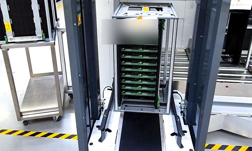
The final design of an automated buffer warehouse often looks straightforward: racks, stacker cranes, conveyors, AGVs...
The final design of an automated buffer warehouse often looks straightforward: racks, stacker cranes, conveyors, AGVs, and a WMS/WCS system.
In a real project, however, the difficult part is not simply putting these technologies together. The real challenge is determining why each piece of equipment is needed, how many units are required, how they should be arranged, and how they should connect with the existing production system.
In this electronics manufacturing project, we needed to design automated buffer warehouses for both the SMT workshop and the insertion workshop. The project had to provide sufficient storage capacity while supporting continuous production inbound flows and material calls from downstream processes. Stacker cranes, conveyors, AGVs, MES, WMS, and WCS also needed to work together as one coordinated material-handling system.
The available workshop height was approximately 3.25 meters, and the system needed to manage at least 128 material categories.
You can view the complete project configuration and workflow in our SMT and insertion workshop automated buffer warehouse case study.
Instead of starting with the question of which automated storage technology to use, we first needed to answer several more fundamental questions:
- How much material actually needed to be buffered?
- How many containers would enter and leave the buffer warehouse each hour?
- What did the SKU inventory distribution look like?
- What type of storage structure would the available space allow?
- How would AGVs interface reliably with the buffer warehouse and production lines?
- How would the software determine when a container should enter storage, where it should be stored, and when it should be retrieved?
The answers to these questions ultimately shaped the entire system design.
We Started with Material Flow, Not Equipment Selection
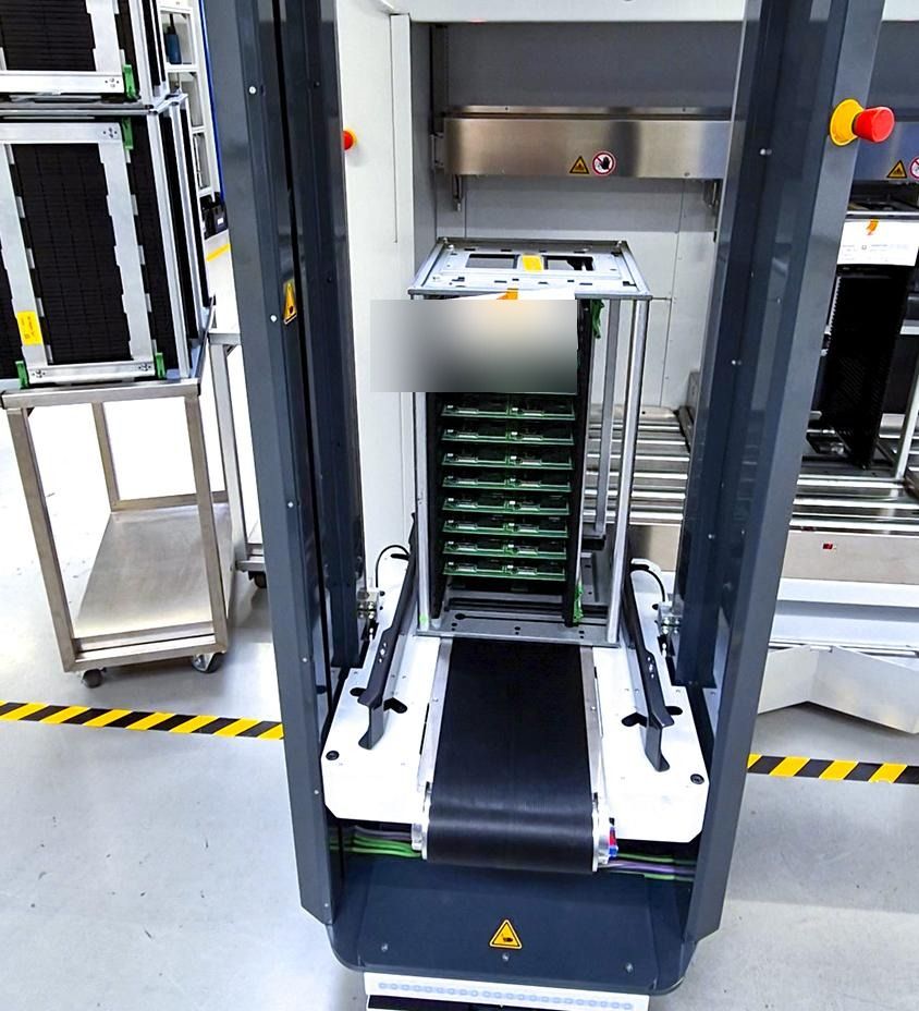
The buffer warehouse in this project formed part of the production logistics process.
Semi-finished products from the SMT and insertion workshops needed to enter the buffer area for temporary storage. When downstream processes required them, the system then had to retrieve the correct materials and deliver them to the designated production area through conveyors and AGVs.
For this reason, our first question was not:
Which type of stacker crane should we use?
It was:
How much material actually moves through the system every hour?
For the SMT workshop, the estimated material flow was approximately:
- Inbound: 34.85 boxes/hour
- Outbound: 34.85 boxes/hour
This meant that under normal production conditions, the buffer warehouse needed to support a combined material flow of nearly 70 boxes per hour.
For the insertion workshop, inbound and outbound flow were each estimated at approximately 30.5 boxes/hour, giving a combined throughput requirement of about 61 boxes per hour.
These figures were important because a buffer warehouse is not only a:
Storage System
It is also a:
Material Flow System
A warehouse might have space for 1,500 containers, but if its automated equipment can process only 30 containers per hour while the production peak requires 60-70, sufficient storage capacity alone will not prevent material congestion.
From the beginning, we therefore treated two metrics separately:
Storage Capacity - How much the system can store
and
Throughput - How quickly the system can move materials in and out
The subsequent equipment selection and quantity calculations were based on both.
Why More Than 1,400 Storage Locations Did Not Determine the Design by Themselves
Based on production takt time and buffering requirements, the estimated inventory model was approximately 1,428 boxes for the SMT buffer warehouse and 1,440 boxes for the insertion workshop.
Looking only at these figures, the design task might seem simple:
Find an automated storage system that can hold around 1,400 boxes.
But that would not have been enough.
Inventory inside a production buffer warehouse is constantly changing.
Some containers are entering storage, some are waiting for production demand, some have completed their required buffering or aging period, and others are already being requested by downstream production lines.
We therefore also needed to consider:
- average buffering time;
- production takt time;
- upstream production fluctuations;
- downstream material call frequency;
- peak inventory levels;
- material batches;
- FIFO requirements;
- aging status;
- empty-container occupancy.
In other words:
1,400 storage locations describe the inventory requirement at a given point in time, but they do not describe the operating capability of the system.
The real design question was:
While holding approximately 1,400 boxes, could the system also continuously handle more than 60-70 inbound and outbound movements per hour?
Only when these two requirements were considered together did equipment selection become meaningful.
Why 128 Material Categories Affected Our Choice of Storage Technology
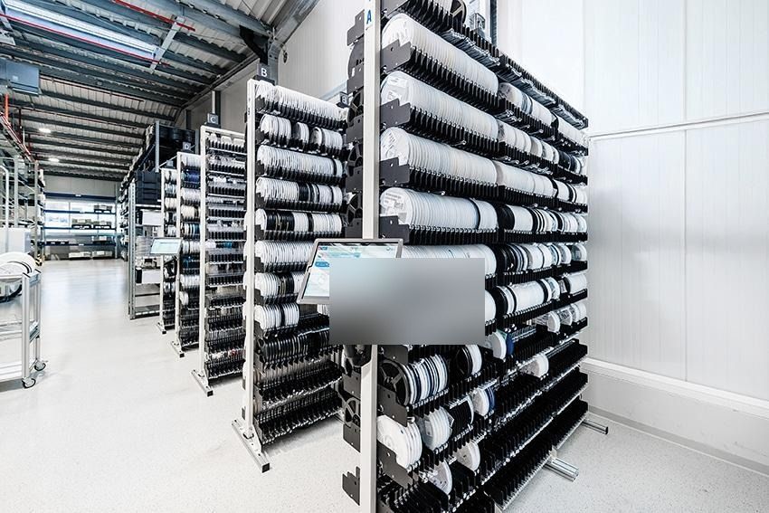
One particularly important project parameter was:
At least 128 material codes.
However, the number of SKUs alone was not the decisive factor.
We also calculated the average inventory depth for each material category.
For the SMT buffer warehouse:
1,428 boxes / 128 categories = approximately 11.15 boxes/category
For the insertion buffer warehouse:
1,440 boxes / 128 categories = approximately 11.25 boxes/category
This meant the project had:
A relatively large number of SKUs, but a comparatively shallow inventory depth per SKU.
That directly affected how we evaluated buffer lines, shuttle-based storage, and box stacker cranes.
Consider two warehouses that both store 1,200 boxes.
Warehouse A:
120 SKUs x 10 boxes
Warehouse B:
20 SKUs x 60 boxes
Although the total inventory is the same, the most suitable storage technology may be very different.
In a deep-lane storage system, if each lane is preferably dedicated to the same SKU while the actual inventory depth per SKU is low, one problem can arise:
The lane is deep, but the inventory is not.
If the remaining positions cannot be efficiently assigned to other SKUs, actual storage utilization decreases.
This project therefore required us to compare several storage approaches.
Simple buffer lines were not well suited to managing at least 128 material categories. Shuttle-based storage also required careful consideration of the inventory depth within each lane, because insufficient depth per SKU could result in underutilized storage positions.
After evaluating the SKU count, average inventory depth, required capacity, and random-access requirements, we selected box stacker cranes as the primary storage and retrieval technology.
The key conclusion was not:
A stacker crane is better than a shuttle system.
It was:
For the SKU profile, inventory depth, and random-access requirements of this particular project, a stacker crane was the more suitable solution.
No automation technology is inherently the best in every application.
The inventory structure determines which technology is actually appropriate.
Why This Project Required Multiple Stacker Cranes
Once the stacker crane technology had been selected, the next question was:
How many units were required?
The simplest approach would have been to determine the quantity from the total number of storage locations.
We did not use that approach.
For this project, the estimated operating capacity of a single box stacker crane was approximately one minute per box.
In theory, that means one machine could complete roughly 60 box-handling tasks per hour.
However, theoretical cycle capacity is not the same as actual system throughput.
Each stacker-crane cycle may include:
- horizontal travel;
- vertical lifting;
- fork extension and retraction;
- box pickup;
- box placement;
- conveyor handoff;
- waiting for upstream or downstream equipment;
- task switching.
In addition, tasks do not arrive at perfectly uniform intervals.
Production changeovers, concentrated inbound activity, or simultaneous material calls can create periods with much higher task density.
The real comparison therefore needed to be between:
Required Throughput
and
Actual Equipment Cycle Capacity
rather than between:
Number of Storage Locations
and
Number of Stacker Cranes
Based on the combined flow requirement of approximately 70 boxes/hour for the SMT area and 61 boxes/hour for the insertion workshop, the initial capacity calculation indicated that each workshop would require at least two stacker cranes to support the required material flow. The final configuration was then refined according to warehouse zoning and the physical layout.
This illustrates one of the most important design sequences in the project:
Material Flow -> Throughput -> Equipment Cycle -> Equipment Quantity
The number of machines was ultimately the result of production-logistics calculations.
A Workshop Height of Around 3.25 m Changed the Storage Design
Another very practical constraint in this project was:
An available height of approximately 3.25 meters.
Traditional AS/RS projects often use building height to maximize storage density.
In an existing production workshop, however, the building conditions are already fixed.
We had to consider not only rack height, but also:
- container dimensions;
- stacker-crane lifting structure;
- conveyor height;
- fire-protection clearances;
- equipment maintenance space;
- safety guarding;
- existing workshop infrastructure.
Our objective was therefore not simply:
Build higher racks.
It was:
Use the available building height as efficiently as possible while preserving the operating and maintenance space required by the equipment.
The final design used four levels of box storage.
The main storage area in the insertion workshop provided approximately 1,560 full-container storage locations, while the SMT area provided around 1,216 storage locations. Compared with the previous floor-based and workshop storage arrangement, the new design increased storage capacity within the same general site constraints.
This also illustrates an important point about retrofit automation projects.
The objective is not always to build the tallest possible automated warehouse.
Sometimes the more important question is:
How can we create more usable storage positions within a fixed floor area and a fixed building height?
Why the AGV-to-Conveyor Interface Mattered More Than AGV Accuracy Alone
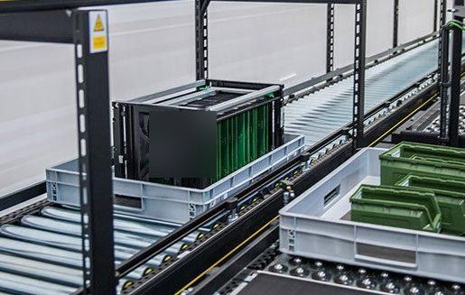
The buffer warehouse was not the only automated part of the project.
Materials also needed to move between the buffer warehouse and production areas by AGV.
This introduced a very specific engineering question:
How could an AGV reliably transfer a container to the conveyor system?
At first glance, the process looks simple:
AGV -> Roller Conveyor
In practice, however, several sources of error need to be considered.
The multi-vehicle positioning accuracy of the AGVs in this project was approximately:
+/-15 mm
The load itself could also shift by approximately:
10 mm
relative to the vehicle.
When these deviations were combined, the actual docking deviation needed to be evaluated at approximately:
+/-25 mm
while the guiding structure allowed a tolerance of approximately +/-30 mm.
The project also required a standardized roller transfer height, with the minimum single-level roller height set at approximately 330 mm.
This shows why asking only:
What is the positioning accuracy of the AGV?
is not enough.
The more important question is:
Under the worst-case condition, what will the final position of the container be relative to the conveyor?
The conveyor receives the container, not the AGV itself.
The interface therefore needed to account for:
- AGV positioning error;
- load-position deviation;
- conveyor width;
- guiding structures;
- roller height;
- photoelectric sensors;
- PLC signals;
- docking confirmation.
Without aligning these parameters during the design stage, a system can easily reach a situation where:
The AGV works correctly and the conveyor works correctly, but the two pieces of equipment cannot transfer containers reliably when connected together.
For this reason, equipment interfaces were treated as part of the system design rather than as installation details to be solved later.
Why the Production Line, AGVs, and Buffer Warehouse Could Not Be Designed Separately
Another issue we wanted to avoid was treating the project as several independent automation systems:
The production line produces the material.
The AGV handles transportation.
The buffer warehouse handles storage.
From an equipment perspective, that separation may appear reasonable.
From a logistics perspective, however, the material follows one continuous process:
Production Line -> Conveyor -> AGV -> Buffer Warehouse
When material is retrieved, the process runs in the opposite direction back toward production.
A mismatch in takt time at any point can affect the entire system.
For example:
If the buffer warehouse retrieves containers quickly but no AGV arrives in time, materials will accumulate on the outbound conveyor.
If an AGV reaches the production line but no buffer position is available, the vehicle may occupy the docking point for too long.
If several production lines issue material calls at the same time, while both the buffer warehouse and the AGV fleet have been sized only for average flow, tasks can accumulate rapidly.
For this reason, we treated:
Storage + Conveying + AGV Transport + Line-Side Buffer
as one material-handling system.
They were not designed as four independent equipment packages.
Why the Software System Had to Be Designed Alongside the Mechanical System
The buffer warehouse needed to answer more than:
Which storage location is currently empty?
The system also needed to know:
- what material was inside each container;
- which production order it belonged to;
- its current inventory status;
- whether it had completed the required aging period;
- which production line was requesting it;
- whether the material met FIFO requirements;
- which storage location was available;
- which piece of equipment should execute the task;
- which AGV should perform the transport.
For this reason, the software architecture connected ERP, MES, WMS, WCS, AGV dispatching, and field-level equipment control, while separating warehouse management, equipment execution, and vehicle dispatching into different control layers.
For example, when a semi-finished product leaves the production line, it is not simply picked up by an AGV.
The corresponding material information must first be created in the system.
The WMS assigns a storage location.
The WCS converts that requirement into an actual storage task according to equipment and location status.
The AGV dispatching system then assigns a vehicle for the transport task.
Once the container enters the buffer warehouse, the inventory status is updated.
When the downstream production line requests the material again, the system must identify the correct container according to material code, batch, inventory status, FIFO rules, and other requirements before executing the reverse logistics process.
This is why we did not treat WMS and WCS as software modules that could simply be added after the mechanical equipment had been installed.
In this project:
Material Flow
and
Information Flow
were part of the same system design from the beginning.
Why We Also Designed the Empty-Container Return Flow
If we look only at the movement of semi-finished products, the logistics process may appear complete once the material has been delivered to the production line.
But the workshop uses reusable containers.
Once the material has been consumed, empty containers remain.
If the automation system only handles full containers, the result can easily be:
Full containers are automated, but empty containers are still moved manually.
In that case, the material-handling loop is not truly closed.
As production volume increases, unmanaged empty containers can also create additional problems, including:
- line-side accumulation;
- blocked aisles;
- additional manual handling;
- interference with AGV traffic;
- shortages of available returnable containers;
- delays in returning empty containers to where they are needed.
For this reason, empty-container handling was not treated as an issue to be solved after implementation.
While designing the full-container inbound, buffering, and production-delivery processes, we also designed a dedicated Empty-Container Flow.
After use, empty containers re-enter the conveyor and storage process and are routed back to the required areas according to production demand, creating a complete circulation loop for both loaded and empty containers.
For an SMT and insertion workshop buffer warehouse like this one, this is an important part of the overall automation concept.
True automation is not simply about removing labor from one section of a material-handling process.
It is about reducing the number of manual handoff points across the entire logistics cycle.
Next Review
Move from article research to a scoped feasibility review.
Use the related products and solution paths below, then send your workflow and layout for a quick engineering review.
Related Solutions
Engineering Review