
Related Products
How We Designed a Composite AGV Feeding and Handling Cell
In this composite AGV feeding and handling project, we needed to solve a typical machine-side automated logistics problem:
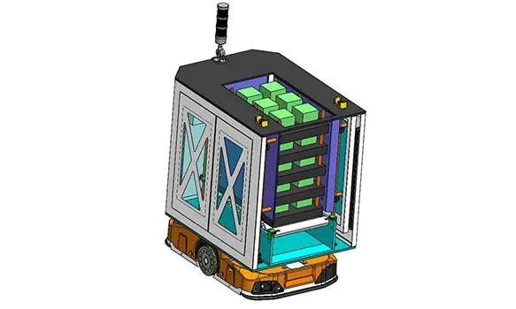
In this composite AGV feeding and handling project, we needed to solve a typical machine-side automated logistics pro...
In this composite AGV feeding and handling project, we needed to solve a typical machine-side automated logistics problem:
How can palletized material move automatically from the surrounding logistics area to the equipment side, complete feeding and transfer operations, and then continue into the next logistics stage?
The project was built around a Composite AGV, receiving module, docking table, and roller conveyor. The system used a 300 kg roller load design basis, with roller speed adjustable from 100 to 300 mm/s. The docking table could buffer 10 trays, while the Composite AGV itself was designed with four tray buffer positions.
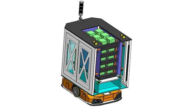
In this application, the Composite Mobile Robot did more than move material from one location to another. It combined mobility, onboard tray buffering, machine-side feeding, and roller-based material handoff in one system.
So the real design question was not:
Can an AGV deliver a tray to the machine?
It was:
How can transport, buffering, docking, and machine-side feeding be combined in a compact automated logistics cell while reducing frequent manual replenishment and equipment waiting?
Why a Basic Point-to-Point AGV Could Not Fully Solve the Problem
If the only requirement were to move trays from a warehouse to a production area, a basic AGV could handle a simple cycle:
Pickup -> Transport -> Drop-off
But the requirement in this project did not end when the vehicle reached the machine side.
After arrival, the system still needed to determine:
- how trays would enter the equipment automatically;
- how many trays could be carried at one time;
- when the equipment needed the next tray;
- where processed trays should wait;
- whether upstream logistics vehicles would need to wait;
- whether feeding and return flow could form a continuous loop.
If the vehicle could only transport material while an operator still had to move the tray from the vehicle into the equipment, the system would achieve:
Automated Transport
rather than:
Automated Feeding and Handling
For this reason, the project required more than a simple transport AGV. It needed a composite mobile system capable of continuing the machine-side material-handling process after transport.
Why We Combined Mobility and Machine-Side Feeding in the Composite AGV
In some automation projects, a system can use:
AGV + Fixed Robot
The AGV handles transport. The fixed robot handles pickup and placement at the machine.
That approach is suitable when task locations are fixed, robot utilization is high, and machine-side handling is relatively complex.
In this project, however, the emphasis was on:
Compact tray feeding and short-distance machine-side transfer.
If every position required another fixed robot, independent buffer, and additional transfer device, the system could become unnecessarily complex.
The value of the Composite AGV was therefore its ability to combine:
Mobility
and:
Machine-Side Handling
on the same mobile platform.
The vehicle could bring multiple trays into the equipment area and then handle feeding or transfer tasks progressively according to actual production demand.
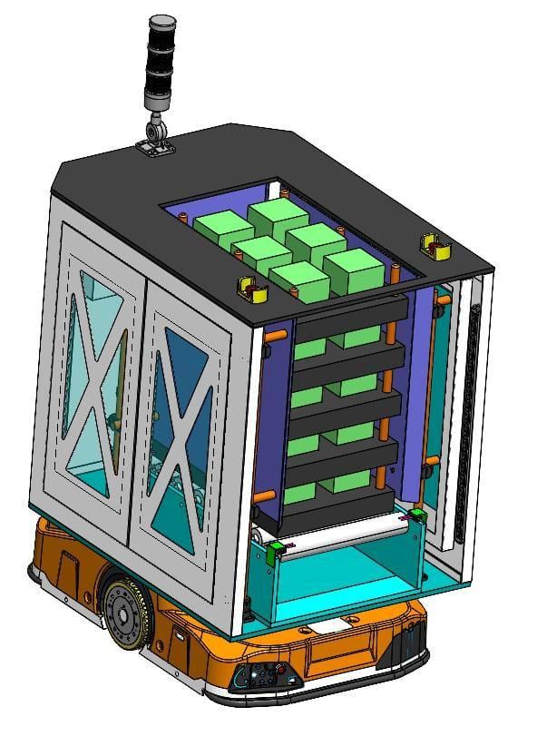
This reduced the need to create a separate logistics cycle for every individual tray movement.
Why Four Tray Buffer Positions Mattered
The Composite AGV was designed with:
4-Tray Buffer Capacity
The purpose was not simply to let the vehicle carry more trays in one trip. More importantly, the four tray positions changed the timing relationship between the mobile system and the production equipment.
If the vehicle could carry only one tray, each feeding action would require:
Vehicle Arrives -> Docks -> Transfers Tray -> Leaves -> Collects Next Tray -> Returns
This would create a large amount of repeated movement.
With four tray positions, the Composite AGV could bring several trays into the equipment area in one trip and then process them progressively according to the production takt.
As a result:
One Vehicle Arrival
no longer corresponded to only:
One Material Handoff
but could support:
Multiple Feeding Cycles
This effectively gave the vehicle a degree of:
Mobile Buffer
capability.
Why Mobile Buffering Reduced Dependence on AGV Response Time
If the production equipment requests the next tray only after it is needed, and the AGV must then travel from a remote location to collect it, equipment waiting time becomes highly dependent on:
AGV Response Time
If the vehicle is already performing another task, the machine may run short of material.
The situation changes when the Composite AGV already carries several buffered trays. When the machine requests the next tray, the vehicle can supply it directly from an onboard buffer position.
This changes the process from:
Production Demand -> New AGV Transport Task
into:
Production Demand -> Local Buffered Material
Only after onboard stock falls to a defined level does the system need replenishment.
The four-tray buffer therefore provides more than physical capacity. It also provides:
Time Flexibility
This is especially valuable in machine-side logistics with frequent feeding requirements and relatively small loads per cycle.
Why the Docking Table Needed Ten Tray Buffer Positions
The docking table in the project could buffer:
10 trays
This is significantly more than the four-tray capacity of the Composite AGV. The two buffer sizes serve different purposes.
The four positions on the Composite AGV function more like a:
Mobile Working Buffer
for current transport and feeding tasks.
The ten positions on the docking table function more like a:
Stationary Logistics Buffer
for temporarily holding more trays between external logistics and the mobile system.
The overall system therefore creates two buffer layers:
Docking Table - 10-Tray Stationary Buffer
Composite AGV - 4-Tray Mobile Buffer
Machine-Side Feeding
This structure reduces the degree to which upstream logistics, the Composite AGV, and the production equipment must remain perfectly synchronized.
Why Two Buffer Layers Could Be More Useful Than Simply Adding More Vehicles
When logistics response is not sufficient, one obvious reaction is:
Add another AGV.
But adding vehicles also introduces:
- more route conflicts;
- more dispatching tasks;
- more charging demand;
- higher equipment investment;
- more complex safety management.
If the real problem is upstream and downstream equipment operating on different cycles, adding vehicles may not be the most effective solution.
In this project, the combination of:
10-Tray Docking Buffer + 4-Tray Vehicle Buffer
could provide material coverage to the production equipment without requiring the vehicle to shuttle continuously.
That is why we first need to determine:
Is the problem insufficient transport capacity, or insufficient buffer capacity?
The two problems should not be solved in the same way.
Why the Docking Table Was Part of the Logistics System, Not Just a Conveyor
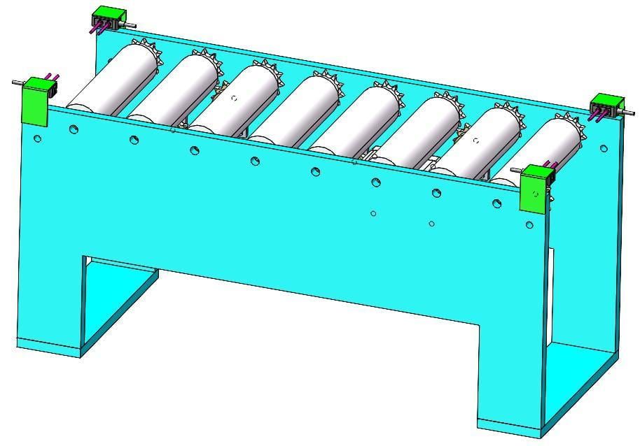
The docking table measured approximately:
1,100 x 7,000 x 1,600 mm
and used the same 300 kg roller load design basis.
From a mechanical perspective, it may resemble a roller conveyor. But its actual functions include:
Receiving
Receiving material from other logistics areas.
Buffering
Holding trays that are waiting for the Composite AGV.
Transfer
Transferring trays onto the Composite AGV.
Return Flow
Receiving material returned from the equipment side.
The docking table therefore serves as the intermediate logistics node between:
Factory Logistics
and:
Machine-Side Logistics
Why Feeding and Return Flow Had to Form a Two-Way Logistics Loop
The project did not only require:
Raw Material -> Machine
After processing or handling, trays also needed to leave the equipment area.
The complete logistics flow was closer to:
Incoming Material -> Docking Table -> Composite AGV -> Machine-Side Feeding -> Processing / Handling -> Composite AGV -> Docking Table -> Next Logistics Area
This means the system must know whether each tray currently represents:
Incoming Material
or:
Processed / Returned Material
because the next destination is different.
The logistics system cannot schedule tasks only from the question: Which position contains material?
It must also know:
What is the status of this tray, and where should it go next?
Why Roller Handoff Was More Important Than Manually Taking Trays Off the Vehicle
Both the Composite AGV and the docking table used roller transfer. This allows material handoff to follow an automatic sequence:
Vehicle Arrives -> Docking Confirmed -> Roller Starts -> Tray Transfers -> Position Confirmed -> Vehicle Continues
If the vehicle can navigate autonomously but an operator still needs to move the tray every time it reaches the docking table, manual handling remains a required interface in the process.
A truly automated feeding system therefore needs to solve both:
Autonomous Movement
and:
Automatic Material Handoff
Automating only the first still leaves the material-handling chain incomplete.
Why 300 kg Was a System Parameter, Not Just a Vehicle Parameter
The project used a:
300 kg Roller Load Basis
This value cannot be used only to select the AGV. The same load condition also needs to be supported by:
- the docking table;
- the roller module;
- the Composite AGV;
- the tray structure;
- the machine-side interface.
Otherwise, the AGV may be able to support 300 kg while another interface supports less. In that case, the usable system capacity is still determined by the:
Weakest Interface
So instead of asking only: What is the AGV payload?
we need to ask:
How much load can the entire material-transfer chain handle reliably from the first interface to the last?
Why the Adjustable 100-300 mm/s Roller Speed Had Practical Value
The roller speed range was designed at:
100-300 mm/s
This does not mean the system should always run at 300 mm/s. Different materials and different transfer stages may require different speeds.
For example, once a tray is fully on the roller section, a higher speed may improve efficiency. As the tray approaches the final positioning point, the system may reduce speed.
This can reduce:
- tray impact;
- final positioning error;
- load movement;
- mechanical collision.
Roller speed therefore affects:
Throughput
Positioning
and:
Transfer Stability
The adjustable speed range gives the commissioning team room to optimize the transfer process for different materials.
Why Vehicle Orientation Changed the Equipment Dimensions and Layout
The project design also used different dimensional bases for different vehicle orientations. For example:
Width-Direction Module: 1,100 x 1,100 x 1,200 mm
Length-Direction Vehicle: 1,400 x 900 x 1,200 mm
This shows that the Composite AGV was not selected as a standard vehicle first and then forced into the site layout.
Vehicle orientation affects:
- aisle width;
- turning space;
- docking orientation;
- tray conveying direction;
- equipment working range.
In machine-side automation:
Vehicle Orientation
is part of the layout design itself.
In a very compact site, changing the direction in which the vehicle approaches may be more effective than simply reducing equipment size.
Why a Compact Layout Did Not Mean Compressing Every Piece of Equipment Together
The Composite AGV had a design size of approximately:
1,450 x 800 x 1,250 mm
One project objective was to create a compact machine-side feeding system. But a compact layout does not mean:
Minimum Distance Between Everything
The design still needs enough space for:
- AGV navigation clearance;
- roller transfer space;
- machine access;
- maintenance access;
- safety zones;
- tray movement envelope.
If every clearance is compressed simply to reduce floor space, the result can include:
- difficult vehicle docking;
- poor maintenance access;
- overlapping safety zones;
- restricted tray transfer.
The more useful objective is therefore:
Minimum Effective Footprint
rather than:
Minimum Physical Gap
Why the Real Design Target Was the Entire Feeding Cycle
If we look only at the Composite AGV, it is easy to describe the project as:
A mobile robot that can transport and feed material.
But the complete logic is:
Material Preparation -> Stationary Buffer -> Composite AGV Replenishment -> Mobile Buffer -> Machine-Side Feeding -> Material Return -> Next Logistics Step
If any one of these stages is unstable, the entire feeding cycle is affected.
So the real design target was not:
A Composite AGV
but:
A Complete Feeding and Handling System Built Around the Composite AGV
That is the main difference between this project and a basic point-to-point AGV transport application.
Planning a Composite Mobile Robot project? Coolyne can evaluate your material flow, tray handling, buffer requirements, docking interfaces, and machine-side operations. Contact Coolyne to discuss your application.
Next Review
Move from article research to a scoped feasibility review.
Use the related products and solution paths below, then send your workflow and layout for a quick engineering review.
Related Solutions
Engineering Review