
Related Products
How We Designed a Composite Robot and AGV Docking Transfer Cell
Learn how Coolyne designed a composite robot and AGV docking transfer cell with roller docking, buffering, two-way flow, and machine-side handling.
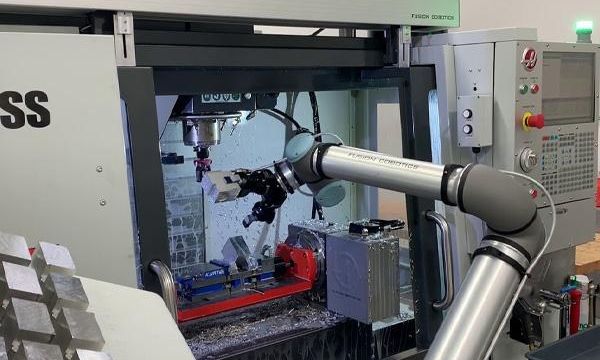
Learn how Coolyne designed a composite robot and AGV docking transfer cell with roller docking, buffering, two-way fl...
In this composite robot and AGV docking transfer project, we needed to solve a typical machine-side logistics interface problem:
How can raw materials from the factory intralogistics system enter the processing equipment automatically, and how can processed materials return to the AGV logistics route?
The final transfer cell was built around a receiving AGV, roller docking table, composite robot, and electric gripper. Both the receiving AGV and the docking table used roller transfer interfaces. The design basis for roller capacity was 300 kg, with an adjustable conveying speed of 100-300 mm/s.
The roller AGV handled automated material transfer between the mobile logistics system and the fixed docking equipment, removing the need for manual handling at the final handoff.
So the real design question was not:
Can the robot move the pallet?
It was:
How can AGV logistics, docking, robot handling, and machine-side processing form a stable two-way material loop within a limited footprint?
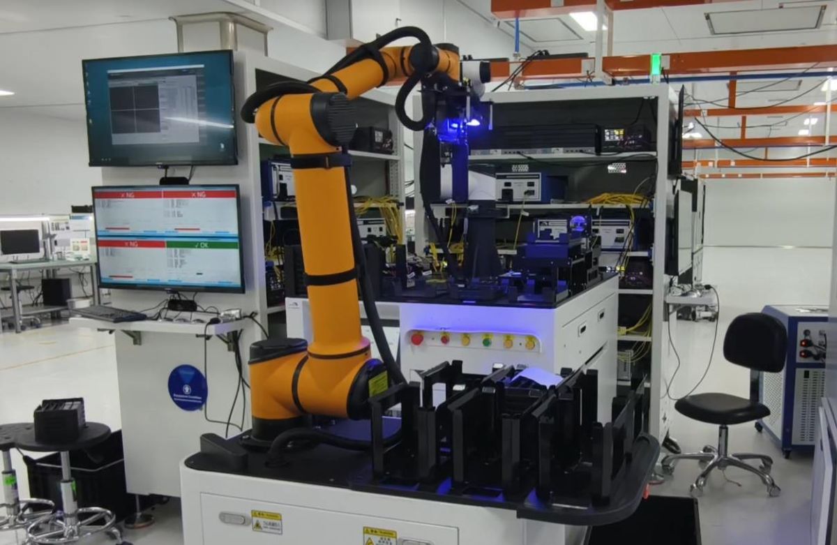
Why We Did Not Let the AGV Enter the Robot Work Area for Every Handoff
The most direct design might appear to be:
The AGV delivers material directly beside the robot.
The robot picks the load directly from the AGV.
After processing, the robot places the load back onto the AGV.
At first glance, this seems to reduce the number of intermediate devices.
But it also forces:
AGV Arrival
and:
Robot Availability
to remain tightly synchronized.
If the robot is busy with another action, the AGV must wait. If the AGV is delayed by another logistics task, the robot may have nowhere to release the completed material.
This would tightly couple two automation systems that naturally operate on different cycles.
For this reason, the project introduced an independent:
Docking Table
as the intermediate material interface.
The logistics relationship changed from:
AGV -> Robot
to:
AGV -> Docking Table -> Composite Robot
After processing, the flow runs in reverse:
Composite Robot -> Docking Table -> AGV
Adding an intermediate node may appear to add equipment, but it reduces the degree to which the two automation systems must respond to each other in real time.
Why the Docking Table Was More Than Just a Roller Conveyor
The docking table in this project measured approximately 1,100 x 7,000 x 1,600 mm and used the same 300 kg roller-capacity basis, with adjustable conveying speed from 100 to 300 mm/s.
At first glance, it may look like a long roller conveyor.
In practice, it performed three different functions:
Transfer
Material can move between the AGV, docking table, and composite robot.
Buffer
Material can remain temporarily at the docking area without requiring the upstream or downstream equipment to respond immediately.
Decoupling
The AGV can operate according to the logistics scheduling cycle, while the composite robot can operate according to the machine-side processing cycle.
The docking table therefore separates:
Logistics Cycle
from:
Machine-Side Handling Cycle
Without this buffer layer, variability in the external logistics system would be more likely to affect the processing equipment directly.
Why the Cell Needed Two-Way Material Flow Logic
This project did not involve only:
Raw Material -> Machine
The design also had to support:
Raw Material -> Docking Table -> Composite Robot -> Processing Equipment
and:
Processed Material -> Composite Robot -> Docking Table -> AGV Logistics
The same docking area therefore had to receive raw material and send processed material back into the factory logistics flow.
The system had to distinguish:
- whether the current pallet contained raw or processed material;
- which direction the pallet should move;
- which buffer position was available;
- whether the downstream equipment was ready;
- whether the roller transfer was allowed to start.
A simple conveyor transfer therefore actually depends on three conditions:
Material Status + Transfer Direction + Destination Status
Only when all three are correct should the system execute the next transfer step.
Why the Composite Robot Handled Machine-Side Operations
The receiving AGV was responsible for connecting the cell with the surrounding factory logistics route.
The composite robot was responsible for:
- picking raw material from the docking table;
- delivering material to the processing equipment;
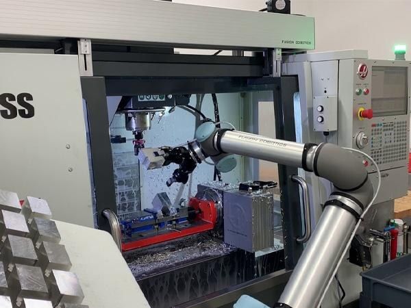
- removing processed material from the machine;
- returning completed material to the logistics transfer path.
This division of responsibilities mattered because:
AGVs are good at moving.
while:
Composite robots are good at precise machine-side handling.
If the AGV were expected to complete every machine-side action, the vehicle would need to do more than navigate. It would also need to adapt to the specific interface of each processing machine.
Conversely, if a fixed robot were expected to handle long-distance transport, its working range would remain limited by its installation position.
The project therefore divided the work into two layers:
Plant-Level Transport -> AGV
and:
Machine-Side Manipulation -> Composite Robot
The docking table connected the two layers.
Why the Composite Robot Needed Four Pallet Buffer Positions
The composite robot system was designed with:
4-Pallet Buffer Capacity
This meant the robot did not have to process one pallet and then immediately wait for the next AGV.
It could temporarily hold several pallets within the cell.
This further reduced the direct dependency between the robot cycle and the AGV cycle.
For example:
The AGV can deliver raw material to the docking area first, while the composite robot processes it according to the actual state of the equipment.
Completed pallets can also wait temporarily in the buffer without requiring the AGV to arrive at exactly the moment the robot finishes its task.
So the four-pallet buffer provides more than:
More Storage
It provides:
More Timing Flexibility
In automated systems, a small amount of well-planned buffer capacity can significantly reduce waiting between upstream and downstream equipment.
Why the 300 kg Roller Capacity Had to Be a Common Interface Condition
The project used a:
300 kg Roller Load Basis
and this value was relevant across the docking table, receiving AGV, and the overall transfer logic.
This means the design cannot stop at asking:
Can the AGV carry 300 kg?
It also needs to confirm:
- whether the docking table can support the same load;
- whether the composite-robot-side transfer mechanism can support it;
- whether the pallet is suitable for roller conveying;
- whether local impact loads can occur during transfer;
- whether the material remains stable when entering or leaving the roller section.
In other words:
System load capacity is only as strong as the weakest interface.
If the AGV can carry 300 kg but the docking table can reliably handle only 150 kg, the entire transfer cell must operate at the lower limit.
Equipment parameters therefore need to be designed around the same material unit rather than optimized independently.
Why the Conveying Speed Needed to Be Adjustable
The roller conveying speed in the project was designed to operate at approximately:
100-300 mm/s
If the only goal were to move material as quickly as possible, the obvious choice would be to run at maximum speed.
Automatic transfer, however, is not always more stable at higher speed.
Different stages may require different conveying speeds.
For example:
In the middle of the roller section, a higher speed may improve transfer efficiency.
Near the final positioning point, a lower speed may reduce impact and improve positioning stability.
For heavier or higher-center-of-gravity loads, lower acceleration and conveying speed may also be appropriate.
So:
Conveyor Speed
is not only a throughput parameter.
It also affects:
Positioning + Stability + Impact
An adjustable speed range therefore gives the commissioning team an important variable for optimizing the final transfer process.
Why Automatic Docking Was About More Than the AGV Reaching the Position
An AGV reaching the docking table does not mean the automatic handoff is complete.
A successful docking sequence requires several conditions:
- the AGV stopping position is correct;
- the AGV roller is aligned with the docking table;
- the conveying heights match;
- the pallet is in a transferable position;
- the destination position is empty;
- the safety zone is clear;
- both control systems have completed the handshake;
- the roller directions are coordinated.
A complete docking process is therefore closer to:
AGV Arrives
then:
Position Confirmed
then:
Docking Permission
then:
Roller Transfer
then:
Load Position Confirmed
then:
Task Completed
rather than simply:
AGV Arrives -> Start Roller
This is why:
Mechanical Interface
and:
Control Interface
need to be designed together in an automatic docking project.
Why the Electric Gripper Still Determined Whether the Robot Could Handle Material Reliably
The end effector in the project used electric gripper tooling for pallet or material pickup and transfer.
A robot arm can have very high repeatability, but the tool that actually contacts the material is the gripper.
The gripper design therefore needed to confirm:
- whether the gripping position was consistent;
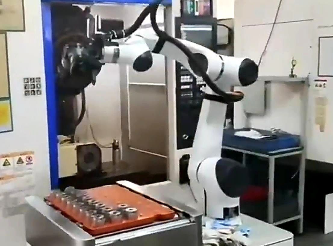
- whether the pallet arrived in a repeatable orientation;
- whether the gripping force was sufficient;
- whether the system needed to confirm the gripping state;
- whether the load could be confirmed as released after placement;
- how the current load should be handled during an abnormal power loss.
Therefore:
Robot Repeatability
cannot replace:
Reliable Gripping
If the gripper cannot handle the pallet consistently, higher robot positioning accuracy alone will not stabilize the entire cycle.
Why We Had to Define the Shared Space Between the AGV, Robot, and People in Advance
The transfer cell included:
- AGV movement;
- composite-robot motion;
- roller transfer;
- operator and maintenance access.
The greatest risk does not come from one machine moving by itself. It comes from multiple moving systems entering the same space.
The project therefore included:
- Emergency-Stop Buttons;
- Safety Light Curtains;
- Alarm Lights;
- Safety Components.
The control logic needed to define questions such as:
- Can the robot enter the shared zone while the AGV is docking?
- Can the AGV leave while the robot is handling a pallet?
- Which devices must stop when a safety light curtain is interrupted?
- What is the material state when the system resumes after a safety stop?
These conditions cannot be added after the equipment is installed.
They need to be part of the transfer sequence from the beginning.
Why a Compact Layout Did Not Mean Placing the Equipment as Close Together as Possible
The composite robot measured approximately 1,450 x 800 x 1,250 mm, while the docking table measured approximately 1,100 x 7,000 x 1,600 mm.
One project goal was to create a compact machine-side transfer cell.
But compact does not mean reducing every equipment gap to the minimum.
The layout still needed space for:
- Robot Working Envelope;
- AGV Docking;
- Safety Zone;
- Operator Access;
- Maintenance Access;
- Tray Transfer Path.
The real target is therefore:
Effective Cell Footprint
not simply:
Minimum Equipment Spacing
If equipment is placed too close together, the footprint may become smaller while safety zones overlap, docking becomes less reliable, maintenance becomes harder, and robot movement becomes restricted.
The result would be a smaller cell with lower availability.
Why the Real Goal Was to Create a Standardized Logistics Interface
The biggest value of this project was not simply eliminating one manual material-handling step.
More importantly, it created a clear machine-side docking interface between the processing equipment and the factory AGV logistics system.
Raw material enters through a defined interface.
Processed material leaves through the same controlled area.
The robot, AGV, and fixed transfer equipment all work around defined transfer positions.
That means if the surrounding logistics system expands in the future, the processing equipment itself does not necessarily need to be redesigned.
The logistics system can continue to connect through the standardized interface.
The transfer cell therefore acts as the bridge between:
Machine Automation
and:
Factory Intralogistics
The core of the project was not to make more robots work at the same time. It was to make different types of automation equipment work together through a clear, stable, and controllable interface.
Planning an AGV-to-Robot transfer cell? Coolyne can evaluate your material flow, docking interfaces, buffer requirements, and robot/AGV coordination. Contact Coolyne to discuss your application and receive a tailored automation solution.
Next Review
Move from article research to a scoped feasibility review.
Use the related products and solution paths below, then send your workflow and layout for a quick engineering review.
Related Solutions
Engineering Review