
Related Products
How We Designed a Shared Composite Robot Machine-Tending Layout for an Unmanned Workshop
In this unmanned workshop AGV machine-tending layout project, we were not planning a standalone robotic workcell. We were planning an entire unmanned...
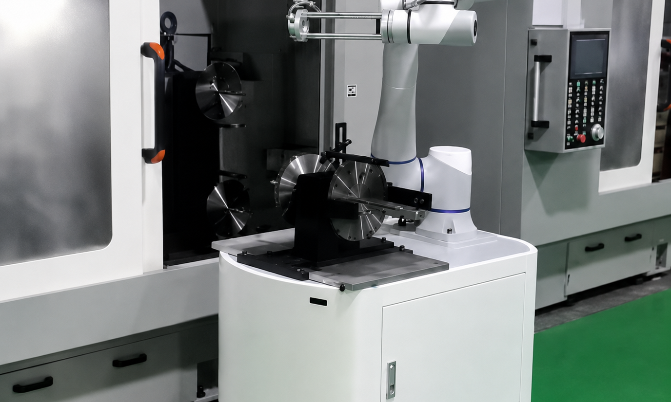
In this unmanned workshop AGV machine-tending layout project, we were not planning a standalone robotic workcell.
In this unmanned workshop AGV machine-tending layout project, we were not planning a standalone robotic workcell. We were planning an entire unmanned machining workshop.
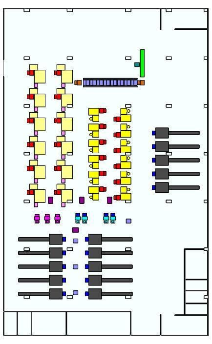
The project scope covered CNC turning, cleaning, hole inspection, downstream processing, tray loading, and automated material transfer between these processes. The design basis included 15 CNC lathes and loading points, 4 cleaning machines, 4 hole-inspection units, 3 tray-loading machines, and approximately 6–7 AGV composite robots.
In this project, the Composite Mobile Robot was not used only for factory transport. It needed to move between multiple equipment groups and perform machine-side loading, unloading, and material transfer according to the production flow.
So the real design question was not:
What robot should be assigned to each CNC?
It was:
How can a limited number of composite robots serve the entire machining workshop while keeping material-transfer distances short and preserving equipment access, maintenance space, and AGV travel paths?
Why This Project Could Not Be Designed as a Collection of Individual Robot Cells
If we look at only one CNC machine, machine tending is relatively straightforward:
Raw Material -> Robot -> CNC -> Robot -> Finished Part
The robot, tooling, safety area, and loading/unloading positions can all be designed around that single machine.
This project was very different.
The workshop included:
- 15 CNC lathes and loading points;
- 4 cleaning machines;
- 4 hole-inspection units;
- 3 tray-loading machines;
- 12 vibratory-bowl feeding units;
- 24 discharge-modification and tray-loading positions;
- 12 tray-feed processing machines;
- 8 cleaning-machine pick-and-place modules;
- 1 AOI inspection machine.
This meant no robot could be treated as an isolated piece of equipment.
Once machining was complete, the material still had to move into the next process.
So the real design object was not:
Robot Cell
but:
Workshop Production Flow
If each workstation were designed independently, the result could easily become a collection of automation islands: individual machines would be automated, but material transfer between them would still depend on people.
Why We Mapped the Production Flow Before Deciding Where the Robots Should Go
The process starts with raw material entering CNC machining and then continues through:
CNC Machining -> Cleaning -> Hole Inspection -> Downstream Processing -> Tray Loading
The composite robots connect these stages and reduce direct manual feeding between equipment groups.
Before deciding robot positions, we therefore had to map the complete production flow.
We needed to know:
- where material enters the workshop;
- which CNC machines complete the first machining step;
- which cleaning equipment receives the parts next;
- how material moves into inspection after cleaning;
- which downstream process follows inspection;
- where final tray loading takes place;
- which process interfaces require mobile robots.
Only after defining:
Where material needs to go
could we decide:
Where the robot should be located
If robots are placed first wherever floor space happens to be available, the process layout can create unnecessary travel and inefficient handoffs.
Why 15 CNC Machines Did Not Mean 15 Composite Robots
The project included:
15 CNC Machines
but the composite-robot planning basis was only:
6-7 Robots
This is one of the most important design decisions in the project.
The most direct automation model would be:
1 CNC = 1 Robot
This makes the control logic simple because each robot is permanently assigned to one machine.
But it also means many robots would spend most of the CNC machining cycle waiting.
CNC processing time is usually dominated by the machining operation itself, while the robot is active mainly during:
Loading
and:
Unloading
If a robot must remain beside one CNC for the entire machining cycle after loading it, robot utilization can be very low.
The project therefore used a shared-service approach.
Composite robots were not permanently tied to individual CNC machines. They were planned to serve multiple machines or process areas within defined service zones.
This changed the robot from a:
Dedicated Machine-Tending Robot
into a:
Shared Workshop Automation Resource
Why Sharing Robots Did Not Mean One Robot Should Serve as Many Machines as Possible
If sharing improves utilization, it may seem logical to let each composite robot serve more and more CNC machines.
But the larger the service area, the farther the robot has to travel and the more likely tasks are to overlap.
For example:
Robot A is loading CNC 1.
CNC 3 finishes machining.
At the same time, Cleaning Machine 1 needs the next load.
If Robot A covers too large an area, it may spend more time traveling between competing requests.
The result can be:
High Robot Utilization
but also:
High Machine Waiting Time
So the real goal of robot sharing is not:
Maximum Machines per Robot
It is:
Balanced Service Coverage
Each robot needs enough work to justify the asset, while service distance and response time remain practical.
Why Robot Station Position Directly Affected Workshop Takt
A composite robot can move, but that does not mean it can perform machine tending from any location.
When it reaches a machine, it still needs a stable docking position and a robot pose that allows the manipulator to complete the required loading and unloading motions.
The layout therefore had to consider:
- AGV travel paths;
- robot docking positions;
- mechanical-arm reach;
- machine loading positions;
- fixture positions;
- tray positions;
- safety areas.
The robot working envelope, transfer points, and AGV routes therefore needed to be planned as one layout.
This means:
AGV Navigation Area
and:
Robot Working Area
cannot be designed separately.
If a robot can reach a CNC but cannot achieve a practical loading/unloading pose after docking, that docking position has little real value.
Why the Shortest Route Was Not Necessarily the Best Layout
A natural objective in an unmanned workshop is to minimize travel distance.
Shorter AGV movement should reduce transport time.
But optimizing only for distance can squeeze out:
- equipment operating space;
- maintenance access;
- robot working envelope;
- safety clearance;
- temporary tray positions.
The robot layout therefore needed to keep service distances short without blocking operators, equipment maintenance, or AGV routes.
The real layout trade-off was:
Travel Distance + Equipment Access + Robot Reach + Safety + Maintenance
not simply:
Shortest Distance
Why CNC, Cleaning, and Inspection Could Not Become Separate Automation Islands
Suppose CNC loading and unloading are automated.
The cleaning machine also has automated pick-and-place.
The inspection machine can also run automatically.
At first glance, all three processes appear automated.
But if:
CNC -> Cleaning
still requires manual transfer, and:
Cleaning -> Inspection
also requires manual transfer,
the overall production flow is still not unmanned.
The core of this project was to treat the different equipment groups as:
One Production System
rather than several independent automation projects.
The composite robot therefore handled:
Inter-Process Material Flow
and created mobile connections between fixed pieces of equipment.
This is one of the situations where mobile manipulation can provide more value than a collection of fixed robot cells.
Why Different Processes Needed Different Robot Handling Logic
Although every process involves moving parts, the machine-side handling sequence is not the same everywhere.
For CNC operations, the key requirements may include:
- precise loading;
- precise unloading;
- alignment with fixtures.
For cleaning, the system needs to consider:
- part position before and after cleaning;
- pick-and-place interface;
- handoff to the next process.
For inspection, the robot needs to ensure:
- the part enters the inspection position correctly;
- the part moves to the correct next process after inspection.
For tray loading, the system needs to manage:
- tray position;
- part arrangement;
- full-tray status;
- replenishment of the next empty tray.
So the workshop cannot rely on one generic instruction such as:
Robot Move Part
The composite robot provides a common mobile platform, but each equipment type still requires its own machine-side handling sequence.
Why Tray Handling Could Not Be Ignored in an Unmanned Workshop
Many machine-tending projects focus on the:
Workpiece
and overlook the:
Tray
that carries the workpiece.
After machining, parts still need to be:
- placed into trays;
- aligned with tray positions;
- monitored for full-tray status;
- removed when trays are full;
- supplied with new empty trays.
The project explicitly included 3 tray-loading machines, 24 discharge-modification and tray-loading positions, and 12 tray-feed processing machines.
This shows that tray logistics itself is a major part of the unmanned production flow.
If the parts can be machined automatically but:
Empty Tray Supply
or:
Full Tray Removal
still depends on manual handling, the workshop still contains a manual logistics break.
Why Cleaning and Inspection Changed the Machine-Tending Layout
The layout would be much simpler if the process were only:
Raw Material -> CNC -> Finished Product
But this project also included two major downstream stages:
Cleaning
and:
Hole Inspection
with:
4 Cleaning Machines
and:
4 Hole-Inspection Machines
This means material leaving the CNC area does not go directly into final trays.
It must travel through additional equipment first.
The composite-robot travel network therefore needs to connect:
CNC Area
then:
Cleaning Area
then:
Inspection Area
then:
Downstream Processing / Tray Loading
The more process steps there are, the less practical it becomes to optimize robot layout around only one machine group.
Why Standardized Machine Interfaces Became More Important as Equipment Count Increased
With only one CNC machine, a custom docking position is manageable.
With many CNC machines plus multiple cleaning, inspection, and tray-handling stations, inconsistent interfaces become much more difficult to manage.
For example:
Machine A loads from the left.
Machine B loads from the right.
Machine C uses a different tray height.
Machine D uses a different positioning method.
The result becomes:
More Machines = More Special Logic
A scalable unmanned workshop should therefore standardize machine interfaces wherever possible.
The goal is for the composite robot to use similar:
- docking logic;
- loading positions;
- tray presentation;
- control handshakes.
The more interfaces can be standardized, the easier it becomes to replicate and expand the robot system.
Why 6-7 Robots Needed Workshop-Level Scheduling
Dispatching is simple when one robot serves only one machine.
Robot 1 always serves CNC 1.
A shared composite-robot system is very different.
The 6-7 robots need to serve the workshop-wide task pool.
At one moment, the system might see:
- CNC 2 requesting loading;
- CNC 6 finishing machining;
- Cleaning Machine 3 waiting for the next batch;
- Inspection Station 1 completing inspection;
- Tray Loading Station 2 requesting an empty tray.
The dispatcher therefore cannot ask only:
Which Robot Is Closest?
It also needs to consider:
- whether the robot already has a task;
- what material it is currently carrying;
- what the next process is;
- whether the destination machine is available;
- whether routes conflict;
- task priority;
- whether a production machine will be forced to wait.
Shared robots therefore require:
Workshop-Level Task Scheduling
rather than several robots operating independently.
Why an Unmanned Workshop Still Had to Be Designed for People
"Unmanned workshop" does not mean people will never enter the area.
Equipment still needs:
- maintenance;
- troubleshooting;
- tool changes;
- cleaning;
- inspection;
- emergency handling.
The composite-robot layout therefore cannot block operator access or machine maintenance.
A good unmanned layout does not hand every square meter to robots.
It clearly separates:
Robot Operation Space
from:
AGV Travel Space
from:
Machine Service Space
from:
Human Access Space
These zones need to work together in both normal production and maintenance conditions.
Why Layout Had to Come Before the Final Robot Count
The project used a planning basis of:
6-7 Composite Robots
rather than one fixed final number.
That is appropriate because whether the workshop ultimately needs six or seven robots cannot be derived from:
15 CNC Machines
alone.
The final number also depends on:
- machine cycle time;
- robot handling time;
- travel distance;
- cleaning and inspection demand;
- tray handling;
- task overlap;
- charging;
- required utilization margin.
The case establishes the workshop layout and equipment-count basis, but it does not publish complete cycle-time data.
At this stage, a more appropriate approach is therefore to:
Define Equipment Zones and Robot Service Coverage First
and then validate whether:
6 Robots
or:
7 Robots
provides the better operating margin once real cycle data is available.
It would not be appropriate to force a fixed robot count that the case itself does not support.
Why This Was Ultimately Not Just an AGV Project
Looking only at the equipment list, the project can easily be described as:
Deploying 6-7 Composite AGVs in the workshop.
But the actual production relationship is:
Raw Material
then:
CNC Machining
then:
Cleaning
then:
Hole Inspection
then:
Downstream Processing
then:
Tray Loading
The composite robots connect the material movements between these processes that would otherwise require manual handling.
So what was really being designed was not:
A Fleet of Robots
but:
An Unmanned Workshop Production Flow
The robots are shared execution resources within that flow.
The project value is therefore not simply that there are more robots in the workshop. It is that CNC machining, cleaning, inspection, downstream processing, and tray logistics are planned as one continuous production system rather than as separate automation islands.
Planning an Unmanned Machine-Tending Workshop?
Coolyne can evaluate your CNC layout, process flow, composite robot coverage, machine-side interfaces, and workshop material-handling requirements. Contact Coolyne to discuss your application.
Next Review
Move from article research to a scoped feasibility review.
Use the related products and solution paths below, then send your workflow and layout for a quick engineering review.
Related Solutions
Engineering Review