
Related Products
How We Designed AGV Material Handling for a Ten-Machine Automatic Test Line
A Coolyne case study on AGV material handling for a ten-machine automatic test line, covering tray buffering, transfer tables, robots, and OK/NG routing.
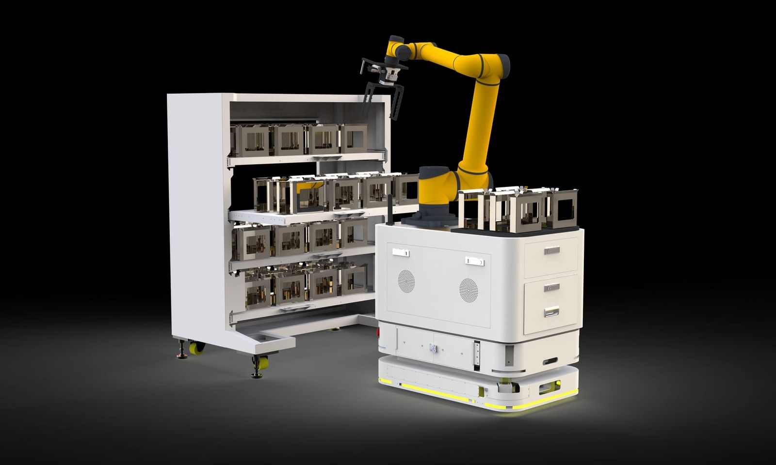
A Coolyne case study on AGV material handling for a ten-machine automatic test line, covering tray buffering, transfe...
In this automatic test line AGV material handling project, we needed to design an automated loading, unloading, and material-handling system for a new test line consisting of 10 test machines.
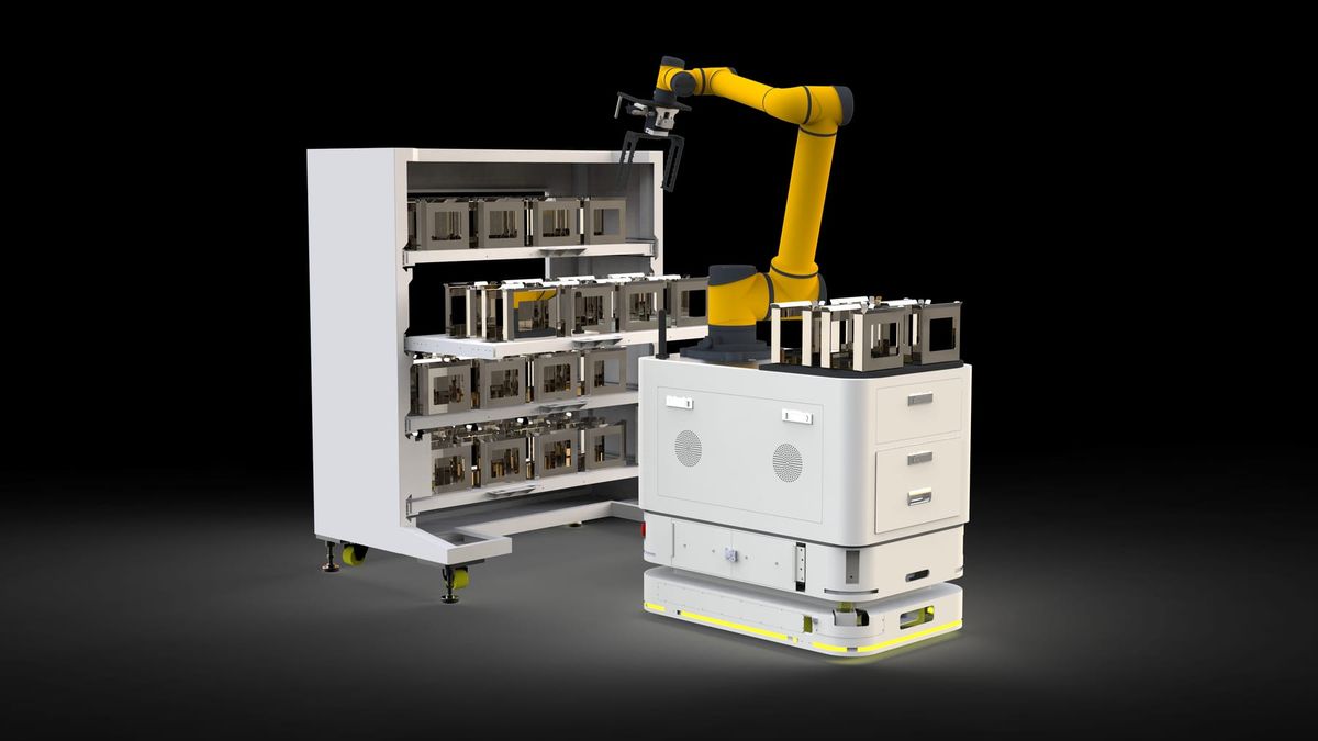
The project handled tray- or magazine-type carriers. Incoming material dimensions were no greater than approximately 280 x 420 mm, with a unit weight of no more than 2 kg. Material handoff at the line side used roller interfaces, and the AGV was designed with four onboard buffer positions. The upper-level system communicated with the logistics system through the SRD standard API.
The complete material flow needed to cover:
Incoming Material Preparation -> Test-Machine Loading -> Automatic Testing -> Test-Machine Unloading -> OK/NG Routing -> Downstream Buffering or Manual Handling
So the real design question was not:
Can an AGV move trays to the test machines?
It was:
How can all 10 test machines receive material continuously without forcing the AGV, composite robot, and test equipment to remain perfectly synchronized for every tray?
That became the key design logic for the system.
Why a 25-Minute Test Cycle Became a 2.5-Minute Logistics Response
Looking at one test machine in isolation, the logistics demand does not appear especially high.
Each machine needs approximately:
25 minutes
to complete one tray test.
If there were only one test machine, the logistics system would need to respond to loading or unloading demand only about once every 25 minutes.
But this project operated:
10 test machines
at the same time.
If the 10 machine cycles are distributed across the line, the overall test area generates a new loading or unloading response approximately every:
2.5 minutes
on average.
These two figures describe different things:
Single-Machine Cycle = 25 min
and
Line-Level Logistics Response ≈ 2.5 min
This shows why process takt and logistics response takt are not the same.
A long test time on one machine does not mean the entire test area produces logistics tasks infrequently. Once multiple independent machine cycles overlap, the logistics system must respond much more often.
So in a project like this, we cannot ask only:
How often does one test machine need material?
We also need to ask:
When all test machines are running, how often does the entire area generate a logistics task?
For this project, the 2.5-minute line-level response was the figure that mattered most for the AGV, composite robot, and buffering design.
Why We Did Not Make the Robot Respond Tray by Tray
The most direct design would be to let the composite robot handle one tray at a time:
Pick One Tray -> Load Test Machine -> Wait for Next Task -> Pick Another Tray
The logic is simple, but the line-level response requirement is approximately one loading or unloading event every 2.5 minutes.
If incoming material were replenished one tray at a time as well:
- the AGV would need to travel more frequently;
- the composite robot would handle upstream material more frequently;
- roller interfaces would be used more often;
- short delays in any one step could be passed directly to the test machines.
Each tray in this project was about 5 cm high, while the maximum permitted stack height was approximately 40 cm.
That allowed one stack to hold:
8 trays
Using the approximately 2.5-minute line-level response as the planning basis, one stack could theoretically cover around:
20 minutes
of test-line operation.
For that reason, we did not design the logistics process only around:
Single-Tray Transfer
Instead, replenishment and composite-robot handling were designed more around:
Stack-Level Transfer
One logistics replenishment could therefore supply multiple trays to the test area rather than forcing upstream logistics to respond after every tray was consumed.
Why Tray Stacking Was Really a Logistics Buffer
Stacking eight trays together may look like a simple packaging or handling choice.
In practice, it changed the timing relationship across the system.
With single-tray delivery, the relationship is closer to:
One Test Demand -> One Logistics Response
Every demand creates an immediate requirement for upstream logistics.
With stacked trays, the relationship becomes:
One Logistics Replenishment -> Multiple Test Cycles
One stack can support the test area for a period of time.
That means the AGV no longer needs to synchronize perfectly with every 2.5-minute response point generated by the test line.
In effect, tray stacking creates:
Time Buffer
not just:
Material Buffer
Because one stack represents a block of production time that can be consumed before another replenishment is needed.
Under the project design basis, an eight-tray stack represented roughly 20 minutes of operating coverage.
So a short AGV delay due to another task would not necessarily cause an immediate material shortage at the test machines.
This is why buffering matters so much in automated logistics.
Its purpose is not simply:
To store more material.
It is:
To reduce how tightly different automated systems must stay synchronized in real time.
Why the Transfer Tables Were the Key Interface Between the Test Line and the AGV
The logistics system included:
Loading Transfer Table
and
Unloading Transfer Table
From an equipment perspective, these may look like simple roller transfer units.
At the system level, however, they provide takt decoupling.
The AGV runs according to the logistics scheduling rhythm.
The composite robot runs according to test-machine loading and unloading demand.
The test machines themselves run on approximately 25-minute test cycles.
These three rhythms cannot be expected to remain perfectly aligned at all times.
If the system required:
AGV Arrives -> Composite Robot Picks Immediately -> Test Machine Needs Material Immediately
then any waiting at one stage would be passed directly to the other equipment.
With transfer tables, the AGV can place material into an intermediate buffer position first.
The composite robot can then collect the material according to the actual state of the test machines.
This partially separates:
AGV Cycle
from:
Robot/Test Cycle
That is why the transfer table is not simply another conveyor section.
It functions as a:
Decoupling Point
between two different automation rhythms.
Why the Composite Robot Handled Test-Machine Loading Instead of the AGV
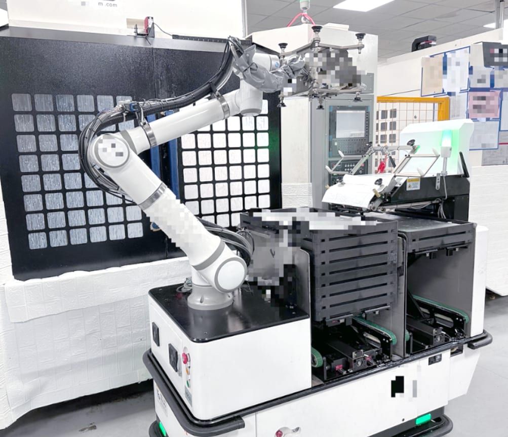
In this project, the roller AGV handled buffer replenishment and the transfer of OK materials, while the composite robot handled tray-stack transfer, test-machine loading, and unloading after testing.
These two pieces of equipment performed fundamentally different jobs.
The AGV is better suited to:
Longer-Distance Material Transfer
between logistics nodes.
The composite robot needed to perform:
Precise Test-Machine Loading and Unloading
including moving material from buffer positions into specific test machines.
If the AGV were required to perform every operation directly, the vehicle would have to interface with every test machine and perform much more complex machine-side handling.
That would push too much localized handling complexity onto the mobile vehicle.
The project therefore created a functional split:
Roller AGV -> Area Logistics
and
Composite Robot -> Machine-Side Handling
The AGV connected the test area to the surrounding logistics system, while the composite robot handled detailed loading and unloading within the test area.
This division was clearer and more practical than forcing one machine type to perform every task.
Why the AGV Still Needed a Roller Interface
Even if an AGV can navigate autonomously to the correct location, the logistics loop is not fully automated if an operator still has to move the tray stack from the vehicle to the transfer table.
That is why this project used a roller AGV and roller handoff at the line side.
The material transfer could then follow:
AGV Arrives -> Docking -> Roller Transfer -> Material Position Confirmed -> AGV Leaves
automatically.
True unmanned logistics must automate both:
Movement
and
Handoff
Moving from Point A to Point B is only part of the transport process. If an operator must receive the load every time the AGV reaches Point B, manual labor remains a required part of the process.
Why Four AGV Buffer Positions Helped Reduce Logistics Waiting
The AGV in this project was designed with:
4 Buffer Positions
This meant the vehicle was not limited to single-position point-to-point transport.
Multiple onboard buffer positions allowed the AGV to carry or temporarily hold more than one material status during the same operating cycle.
For example, the scheduling system could more flexibly manage:
- material waiting for replenishment;
- OK material that had completed testing;
- material moving between different transfer points;
- later logistics tasks already assigned to the vehicle.
The case does not specify a fixed assignment for each of the four buffer positions, so the key point is their system-level function:
Onboard buffer positions reduce the need for the AGV to complete one handoff and immediately return for another load.
At the same time, additional buffer positions increase scheduling complexity.
The system must know:
- which position is currently available;
- which position is occupied;
- which task owns the material in that position;
- which onboard position should be used for the next handoff.
So:
More Buffer Positions ≠ Only More Capacity
They also provide:
More Flexible Task Scheduling
Why Test Results Had to Route OK and NG Material Immediately
One of the biggest differences between this project and ordinary production transport is that the material route depends directly on:
Test Result
Once testing is complete, material can follow at least two different paths:
OK
and
NG
OK trays can move into the approved-material buffer or downstream logistics flow.
NG trays may require:
- retesting;
- fixture inspection;
- manual handling.
So the logistics system cannot know only:
The test is finished.
It must also know:
What was the test result?
Otherwise, the system cannot decide where the tray should go next.
The relationship between the test equipment and the logistics system is therefore not simply:
Machine Finished -> AGV Pickup
It is closer to:
Test Completed -> Result Generated -> Route Decision -> Material Transfer
In other words:
The quality result itself becomes a logistics routing condition.
That is one of the main differences between an automatic test line and ordinary point-to-point AGV transport.
Why NG Material Could Not Simply Follow the Same Route as OK Material
If all trays were transported to one common location after testing and operators then separated OK and NG material manually, much of the automation value would be lost.
More importantly, NG material already has a different downstream process.
It may need:
Retest
or:
Fixture Inspection
or it may need to move directly to a:
Manual Receiving Point
NG material is therefore not simply another normal downstream flow.
It is an:
Exception Flow
The system design must therefore handle both:
Incoming -> Test -> OK -> Downstream
and:
Incoming -> Test -> NG -> Exception Handling
If exception logistics are not designed in advance, the project can easily end up with a system where normal products are automated but NG products still require ad hoc manual handling.
For an automatic test line, that would leave a clear manual logistics break in the process.
Why MES Signals Had to Be Part of the Robot Loading Logic
The composite robot did not simply see an empty test-machine position and load material automatically.
Its loading and unloading sequence needed to coordinate with:
MES Signals
The reason is simple.
A physically empty position does not necessarily mean the system is ready for immediate loading.
The upper-level system may still need to know:
- what the current test task is;
- which machine needs the next tray;
- whether the incoming material matches the correct test task;
- whether the previous test result has been returned;
- whether the current machine allows the tray to be removed.
Material movement therefore cannot be determined only by:
Physical Position
It also needs:
Production/Test Status
before the robot is allowed to act.
This turns automatic test-line logistics into:
Material Flow + Test Information Flow
Only when these two flows remain aligned can the robot know which tray belongs in which test machine and where it should go after testing.
Why the SRD API Was Part of the Project Design, Not a Software Detail for Later
The project explicitly used the:
SRD Standard API
as the basis for communication with the upper-level system.
This matters because the logistics system cannot operate in isolation.
When the test line generates a demand, the upper-level system needs to be able to:
- create or transmit a task;
- coordinate test-equipment status;
- connect with logistics scheduling;
- receive execution results.
If these interfaces are considered only after the mechanical equipment has already been installed, the project can end up with a situation where every machine works independently but the systems cannot exchange task status correctly.
That is why software interfaces need to be defined during the design stage.
An automated logistics task is not only:
Move Material
It also needs to define:
When
Which Material
Which Machine
Which Result
Which Destination
These conditions ultimately have to be coordinated through system data.
Why the Layout Could Be Simplified Further If the Site Distance Allowed It
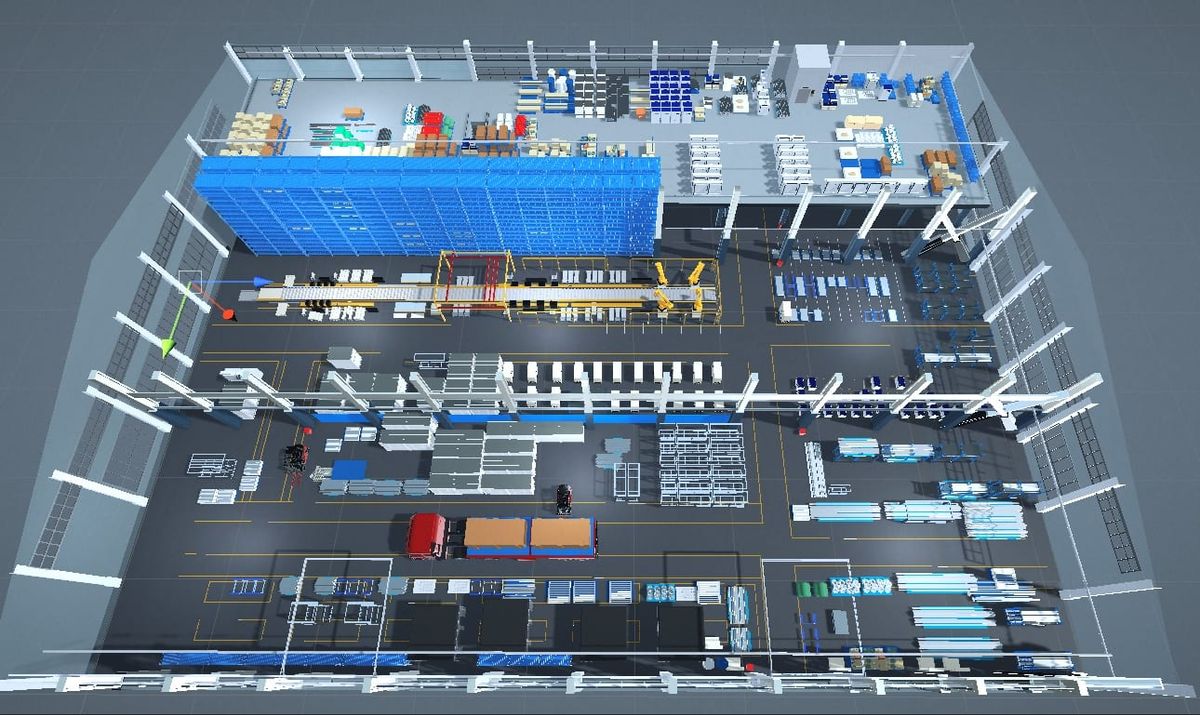
Another useful design point in this case was that the roller-line layout could be simplified further if the Incoming Area and Transfer Area were close enough.
The purpose was to reduce cost where an additional transport segment did not create enough value.
This shows that automation design is not:
The more equipment, the more complete the solution.
A well-designed system should ask:
Does this logistics node actually need another independent piece of equipment?
If two areas are only a short distance apart, adding another conveyor section may provide little operational benefit.
Removing unnecessary equipment can reduce:
- initial investment;
- the number of control nodes;
- potential failure points;
- maintenance workload.
So automation design needs to answer not only:
What should be automated?
but also:
What does not need another layer of automation?
For this project, the goal was not to add as much equipment as possible. It was to make the AGV, buffers, composite robot, test machines, and upper-level systems work together as simply and reliably as possible while meeting the logistics response requirements of all 10 test machines.
Next Review
Move from article research to a scoped feasibility review.
Use the related products and solution paths below, then send your workflow and layout for a quick engineering review.
Related Solutions
Engineering Review